Using Analog Sensors with a Raspberry Pi
January 2, 2022 | 3 minutesIn This Post
The general-purpose input-output (GPIO) pins on a Raspberry Pi only support digital signals natively. However, many sensors, peripherals, and other microcontrollers communicate using analog signals. The analog signals need to be converted so that the Raspberry Pi can understand them. Connecting a device that communicates with analog signals directly to a Raspberry Pi will either throw an error or cause wildly inaccurate data readings from the device.
Let's look at the differences between analog and digital signals and how we can convert them.
What's the Difference Between Digital and Analog Signals?
Digital signals are binary and only support two states: on (1) and off (0). The on-state is equivalent to the maximum voltage level of the device, so it's 5V for a Raspberry Pi. The off-state is 0V. This is different from analog signals, where voltage differences can provide an infinite range of signal values. The Raspberry Pi only knows how to respond to the on and off states, but not the "in-between" states represented by analog signals.
To get analog devices to work with the Raspberry Pi's digital GPIO pins, you need to convert the analog signals using an analog to digital converter.
What is an Analog to Digital (ADC) Converter?
An ADC does what it sounds like: it converts analog signals to digital signals. It does this by sampling an analog voltage at a point in time and converting it into a digital signal representing the analog voltage.
ADCs come with different resolutions, and the resolution determines the number of discrete analog levels that it can detect. More specifically, the resolution determines the smallest signal and the size of incremental signal changes that the converter can detect. For example, a 10-bit analog to digital converter can detect 1,024 (or 2^10) analog levels, while a 16-bit converter can detect 65,536 (or 2^16) analog levels.
How to Convert Analog to Digital Signals with a Raspberry Pi, an Analog Sensor, and an ADC
The following diagram shows the connections needed between an analog sensor, such as a temperature sensor, an MCP3008 analog to digital converter, and a Raspberry Pi 3B.
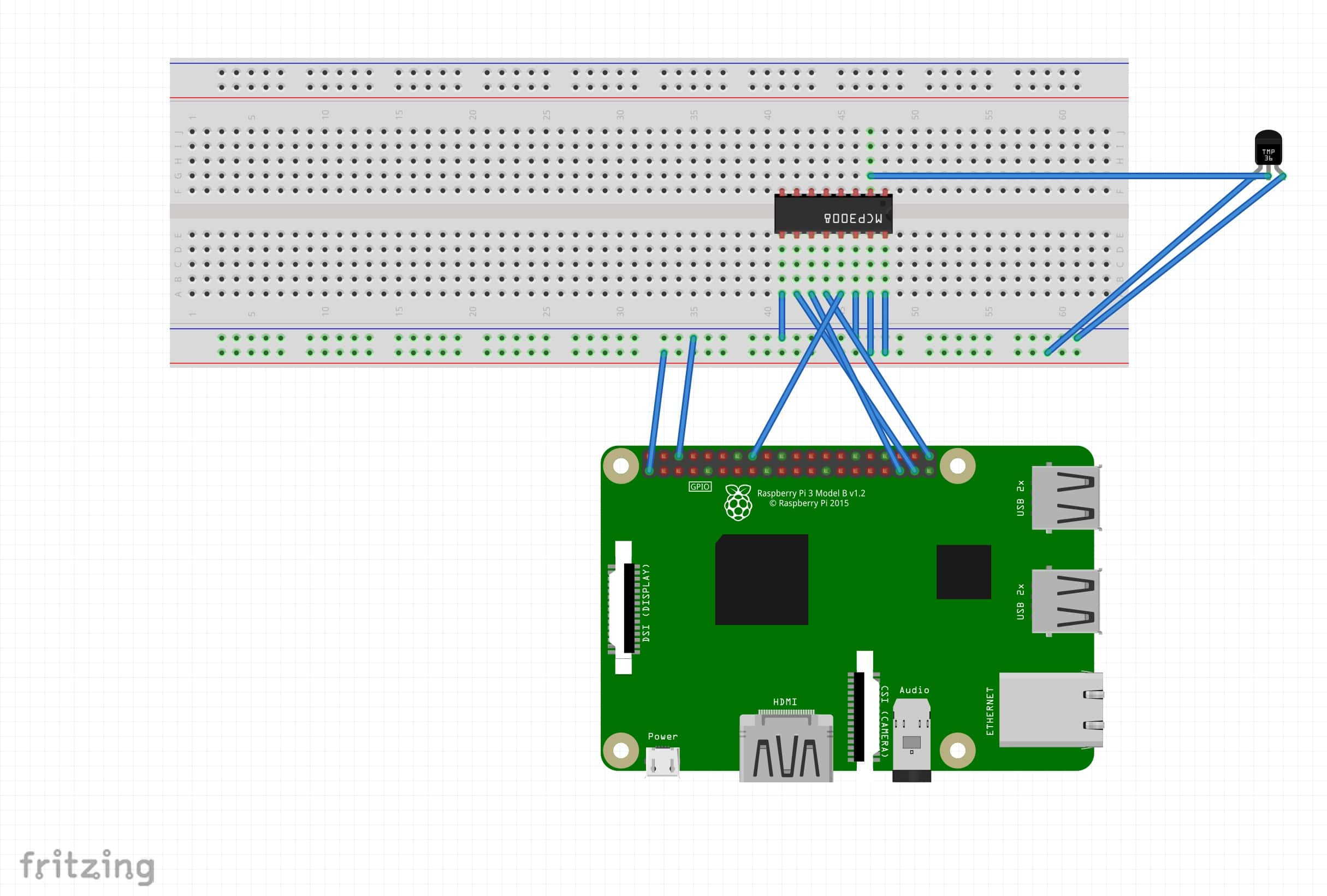
Here are the pin connections that are needed. You can also view a more detailed diagram on Flux.ai.
Connecting the Raspberry Pi to the MCP3008 (ADC)
Here are the pin connections needed to connect the MCP3008 to power, ground, and the Raspberry Pi's SPI pins:
- Power rail to VREF pin on MCP3008
- Power rail to VDD pin on MCP3008
- Ground rail to DGND pin on MCP3008
- Ground rail to AGND pin on MCP3008
- Raspberry Pi SPI Header 26 pin to CS pin on MCP3008
- Raspberry Pi SPI Header 19 pin to DIN pin on MCP3008
- Raspberry Pi SPI Header 21 pin to DOUT pin on MCP3008
- Raspberry Pi SPI Header 23 pin to CLK pin on MCP3008
Here are the pin connections needed to connect the temperature sensor to power, ground, and the MCP3008. It uses one of the 8 channels on the MCP3008 to communicate; this leaves 7 channels open for additional analog sensors.
- Power rail to VCC pin on the temperature sensor
- Ground rail to GND pin on the temperature sensor
- CH 1 pin on MCP3008 to OUT pin on temperature sensor (it could connect to any of the 8 channels on the MCP3008)
After making the connections above, you'll be able to access the sensor data on the Raspberry Pi using your programming language of choice.
Suggested Analog to Digital Converters
I've used the following analog to digital converters in my Raspberry Pi projects. Both work well, but the ADS1115 is more precise. Disclosure: I get commissions for purchases made through links in this post.
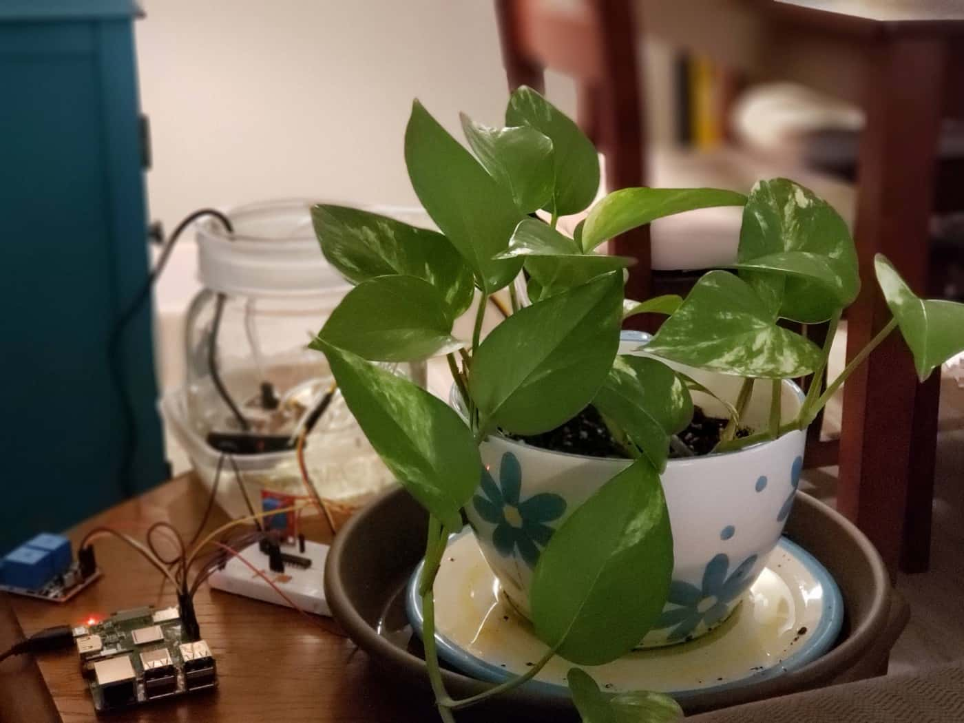
Once you have analog sensor data flowing, you can use MQTT to share that data among multiple devices or build something practical like an automated plant watering system.