How Do Serial Peripheral Interfaces Work?
December 5, 2021 | 5 minutesIn This Post
I'm a software engineer by trade, but enjoy working on IoT projects in my spare time. This post is part of a new series exploring hardware communication concepts as a way to improve my projects.
A Serial Peripheral Interface (SPI) is an interface bus that can be used to connect microcontrollers to peripherals like sensors. It's used for communication between computers and peripherals like sensors (temperature, pressure, potentiometers, etc.), memory cards, and game controllers. An SPI bus is fairly small, so it's often used in smaller IoT devices and embedded systems.
How Do Devices Communicate Using a SPI?
With SPI, data is transferred synchronously as a single stream. This means that it's sent as a continuous stream of data signals. The data signals are sent alongside timing signals (generated by a clock controlled by the master device) that make sure that the transmitter and receiver stay in sync with each other. The SPI uses separate connection lines for the clock and the data. Once the connection is synchronized over the clock lines, data transmission begins.
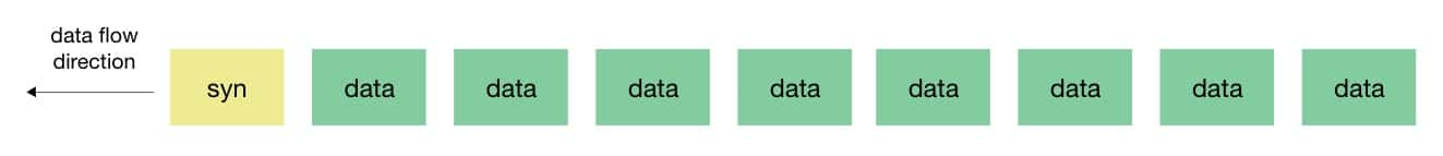
Data transferred over an SPI is organized into blocks that are sent in regular intervals. The blocks are preceded by syn (synchronous idle characters). The remote device uses the syn characters to decode and synchronize the connection with the transmitter. Once the connection between the devices is synchronized, the data is transmitted.
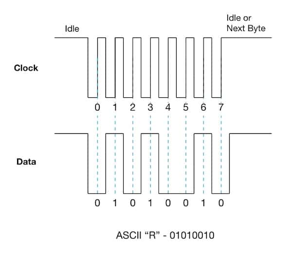
Due to the use of a clock line and the synchronous streaming of the data, there's no need for start and stop bits to be added to the ends of the bits. This contributes to the quick data transfer rate.
All devices connected via SPI must be set to the same clocking though. Otherwise, errors will occur where bits are lost and the data becomes corrupted. Due to the clock timings, it's best to use SPI when the devices transmitting data are no more than 32 feet apart. At longer distances, you can run into issues where the data cannot be sent between the devices during a single clock signal, which will cause the data to become corrupted.
SPI is useful when you need to transfer a lot of data quickly between computers or parts of computers that are relatively close to each other.
Connecting Devices Over an SPI
When using a Serial Peripheral Interface, there's always one master device that controls one or more slave devices. Each device has three common lines:
- MISO (Master In Slave Out) - Used to send data from a slave device to a master device
- MOSI (Master Out Slave In) - Used to send data from a master device to a slave device
- SCK (Serial Clock) - Timing signals that synchronize data transmission between devices
- SS/CS (Slave Select/Chip Select) pin - Exists on each device and is used by the master device to signal that it's ready to send or receive data
The pins can be named differently depending on the manufacturer. Sometimes, the MISO and MOSI pins are combined into a single pin. MISO is sometimes called SDI (Serial Data Input) and MOSI can be called SDO (Serial Data Output). The SS/CS pin is often called a CE (chip enabled) pin on Raspberry Pis and other microcontrollers. When in doubt, check the datasheet for the sensor to determine which pins are correct for transferring data using the SPI.
Sending and Receiving Data Using an SPI
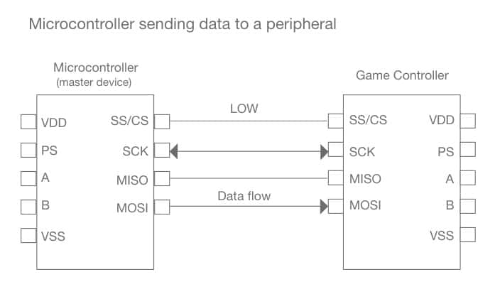
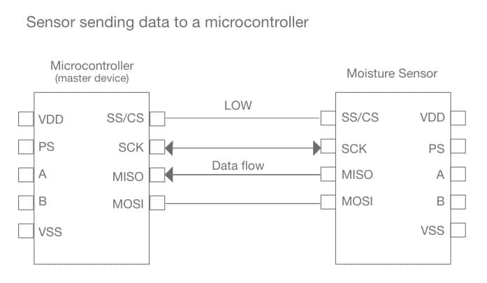
When the master device is ready to send or receive data, its SS/CS pin needs to be set to LOW and remain LOW until communication stops. This lets the slave device(s) know that the master device wants to start communicating with them.
If the master device is sending data, then the slave device(s) will receive data on their MOSI pin.
If the master device requests data, then the slave device(s) will send data on their MISO pin.
SPI Connection Architectures
The way that data is shared between the master and slave device(s) is based on the number of slave devices and the architecture used to connect the devices.
- Single connection
- Daisy chain connection
Single Connection
The single connection architecture is used when there's just one slave device to connect to a master device. This is the simplest architecture. The MOSI, MISO, SCLK, and SS/CS pins on the slave device are connected to the same pins on the master device.

Daisy Chain Connection
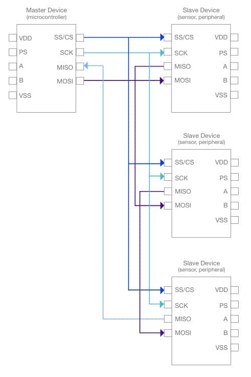
The daisy chain connection architecture is used when connecting multiple slave devices to a master device. The single SS/CS pin on the master device is used to transfer data to each of the slave devices. Instead of connecting the master device to each slave device individually, this architecture:
- Connects the MOSI pin on the master device to one of the slave device's MOSI pins.
- The MISO pin on that slave device connects to the next slave device's MOSI pin until you get to the last slave device.
- The last slave device's MISO pin is then connected to the master device's MISO pin.
This means that the data from the master is sent from one slave device to another instead of directly to each slave device from the master device. The SCLK and SS/CS pins on the master still need to be connected to each slave device so that the slave devices can be synchronized with the master's clock signal and know when communication is being initiated. The master device needs to send enough clock signals to allow the data to reach the last slave device in the chain.