Adding LEDs to a Cross-Stitch Project
December 28, 2021 | 11 minutesIn This Post
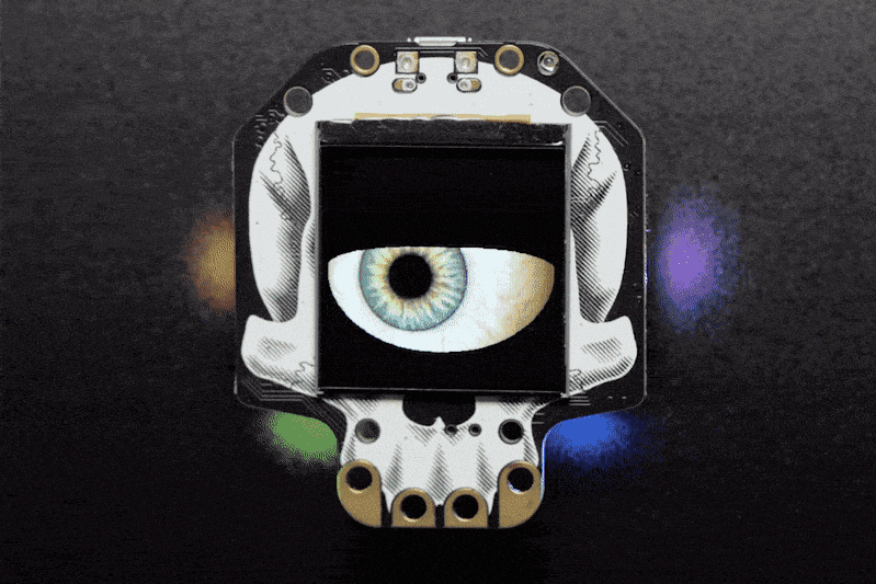
Over the past year, I've been working on cross-stitch projects in the evenings as a way to relax. I recently came across the Arduino LilyPad and was curious about using conductive thread to sew a circuit. So, I decided to use one to add LEDs to a cross-stitch project. I thought it would be a nice touch for this circuit board pattern and am happy with the finished project.
This is a great beginner sewable electronics project, so if you like to sew but are new to electronics, here's what you need to know to create a similar project.
Getting Started
Choosing a Cross-Stitch Pattern
I chose this circuit board pattern for my project and went with the black fabric because it helps hide the board and battery in the completed project. You can select any cross-stitch pattern for your project. Just keep in mind that the LEDs require stitches on each terminal (positive and negative) and that the conductive thread is a silver color, so it's best to select a pattern where the silver stitches won't detract from the completed picture.
Parts List
For this project, you'll need the following items. Disclosure: I get commissions for purchases made through links marked as "Amazon affiliate links" in this post.
- Cross-stitch fabric and thread (based on your pattern selection)
- Arduino LilyPad USB
- LilyPad LEDs (available in many colors)
- Battery to power LilyPad, which could be either:
- A rechargeable Lithium Polymer (LiPo) battery
- A non-rechargeable CR2032 battery and battery holder
- Conductive thread
- Micro USB cable that can transfer data
- Fabric glue to secure the conductive thread once you're finished
Selecting the LilyPad Board
There are multiple versions of the Arduino LilyPad circuit board, and most of them will work on this project. However, not all of the LilyPad boards are the same:
- Some boards are more likely to have working bootloaders than others.
- The LilyPad LilyMini ProtoSnap board comes pre-programmed and cannot be re-programmed.
A bootloader is a program responsible for booting up the Arduino and publishing programs to your board. If the bootloader doesn't work, you can't put programs onto your board.
When I started working on this project, I bought a LilyPad from Amazon because it was the cheapest option. The bootloader is either missing or broken, though, so I haven't been able to publish programs to it (something I plan to fix at some point). With some research, I discovered this tends to happen more frequently with cheaper boards. You can add or fix the bootloader, but it's tricky for beginners. Keep this in mind as you compare and purchase your board. The LilyPad I linked to above from SparkFun worked for me right out of the box.
Steps
The steps that I followed for completing the project are as follows:
- Plan the circuit
- Cross stitch the pattern
- Program the LilyPad
- Stitch the LEDs into the cross-stitch picture as desired and connect them to the LilyPad
- Lightly brush the fabric glue over the conductive thread once satisfied with the project to protect the thread and keep them in from moving around
It's helpful to program the LilyPad before you connect the LEDs because it can become awkward to connect it to the computer once it's stitched to the fabric.
Planning the Circuit
I recommend thinking about the LEDs at the outset and deciding where you want to put them before starting to cross-stitch (although it's ok if you do this after you've sewn the picture).
Thinking About Sewable Circuits
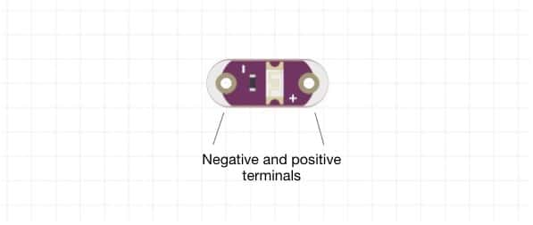
Each LED requires at least one stitch of conductive thread on each terminal (positive and negative), so you'll need to leave space for these stitches in the picture. Ideally, you should wrap the thread through the terminal multiple times before stitching it into the design to ensure maximum connectivity between the terminal and the thread (I wrapped it three times for each terminal).
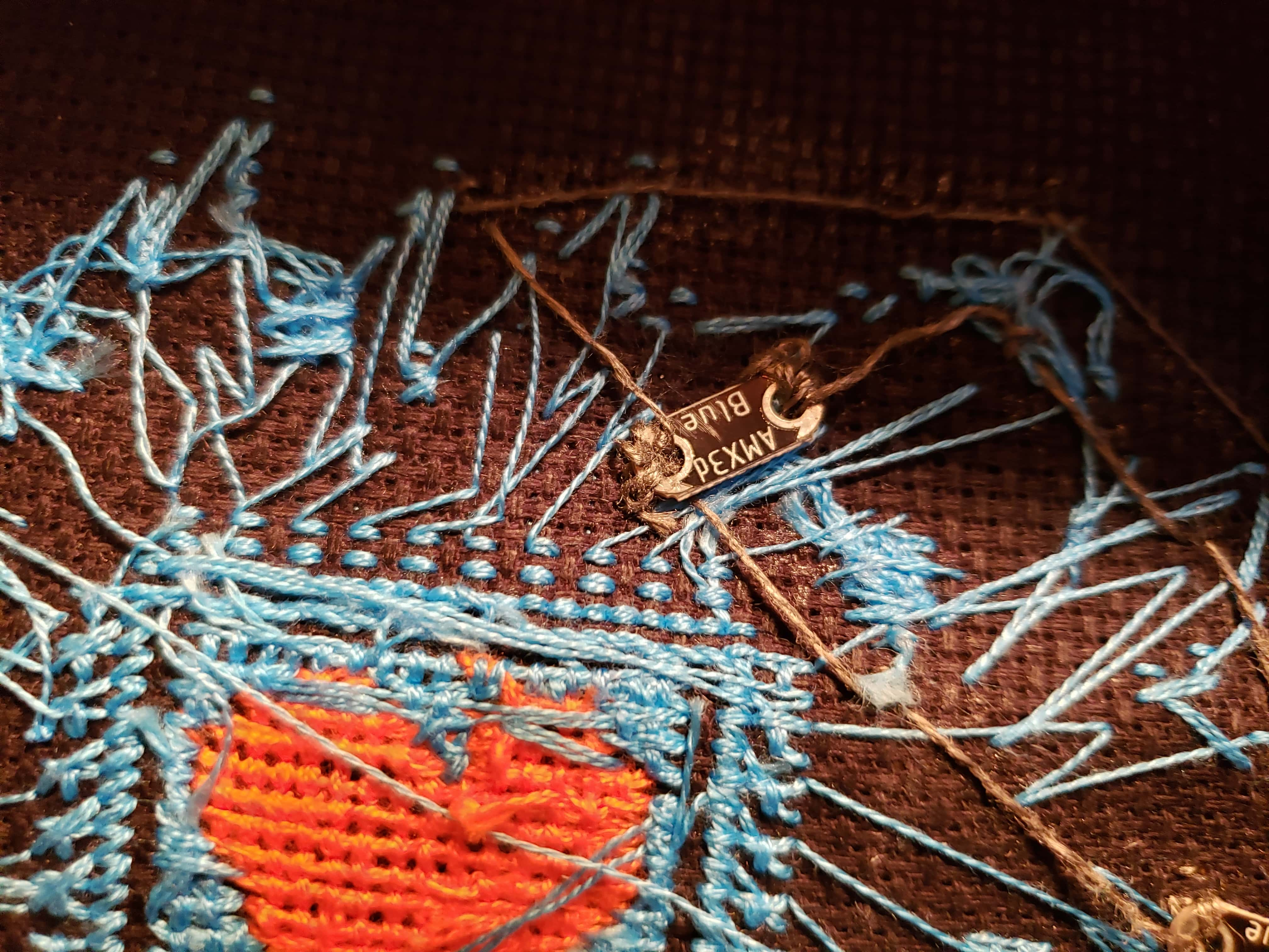
When stitching the LEDs, you'll need a separate piece of conductive thread for connecting the positive and negative terminals to other LEDs or the LilyPad. Choose a long length of thread to start with. Breaks in the thread can cause connection issues that prevent your LEDs from lighting up correctly.
Short Circuits
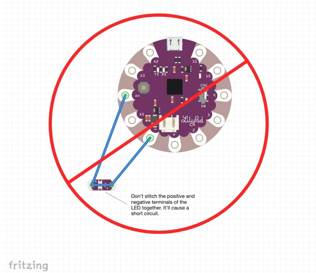
A short circuit will cause a break in your circuit and prevent your LED lights from lighting up. It can also potentially fry your LilyPad or even electrocute you, so it's essential to be careful when wiring up the LEDs. To avoid short circuits, be mindful of the following:
- Don't cross the positive and negative strands of conductive thread.
- Don't stitch the positive to the negative terminals of an LED together.
- Never work on an electronics project on a metal surface.
- Keep the tail of the conductive thread short when you tie it off to avoid threads from accidentally touching other threads or the battery.
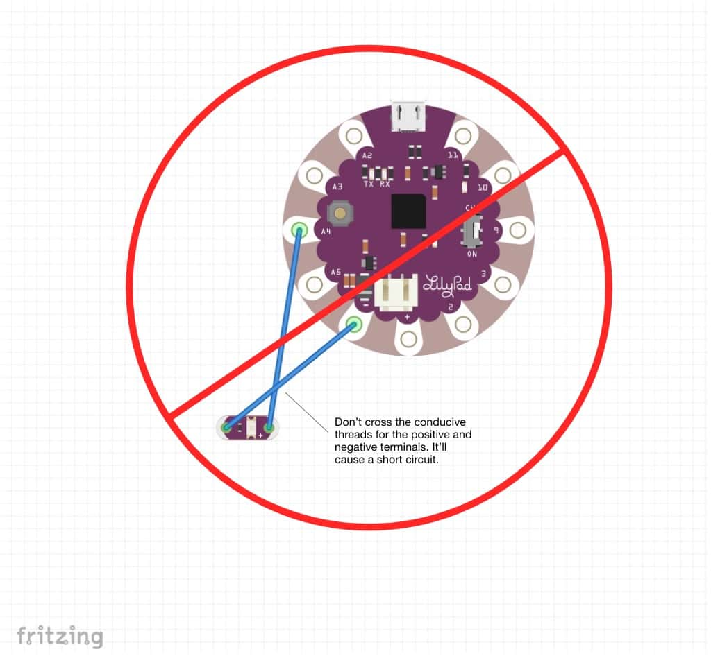
Planning your circuit will help you ensure that you leave enough space for the LEDs and that your wiring is planned in a safe way that won't create short circuits.
Considerations for Wiring the Circuit
The general-purpose input-output (GPIO) pads are configured as follows for the Arduino LilyPad USB board. Different versions of the LilyPad may have different GPIO configurations. For the purposes of this project, you can use analog or digital pads on the board.
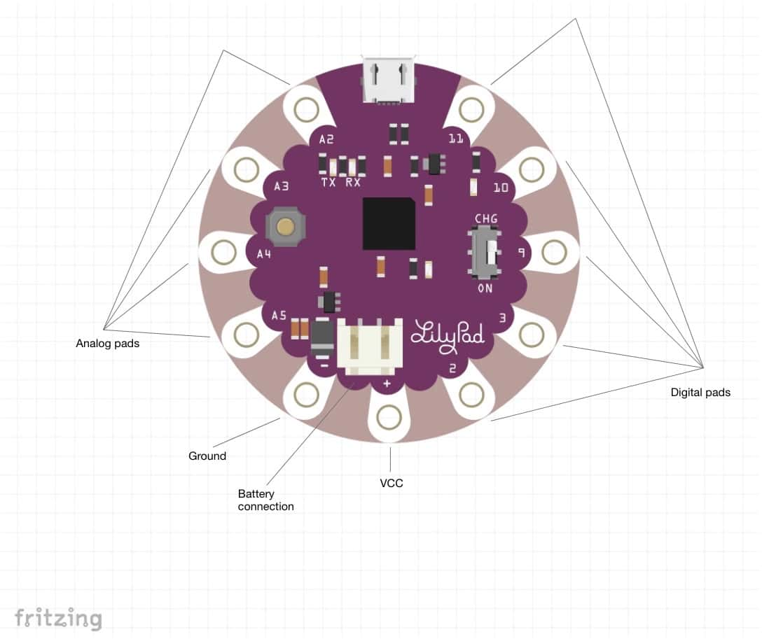
There are a few ways to connect the LEDs to the LilyPad.
Connect Single LEDs
The most straightforward approach is to connect a single LED to the LilyPad by connecting:
- The positive terminal on the LED to an analog or digital pad on the LilyPad
- The negative terminal on the LED to the ground pad on the LilyPad
This approach will allow you to program each LED separately for maximum control. It also adds complexity when designing your circuit so that none of the positive and negative conductive threads cross.
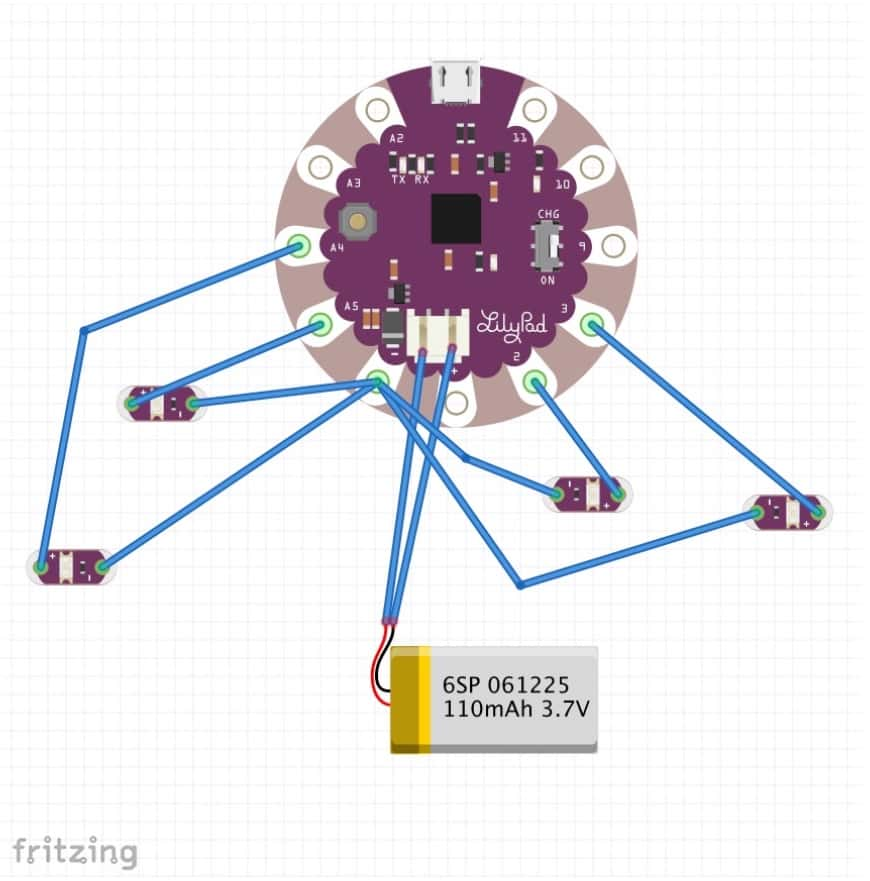
Daisy Chain the LEDs
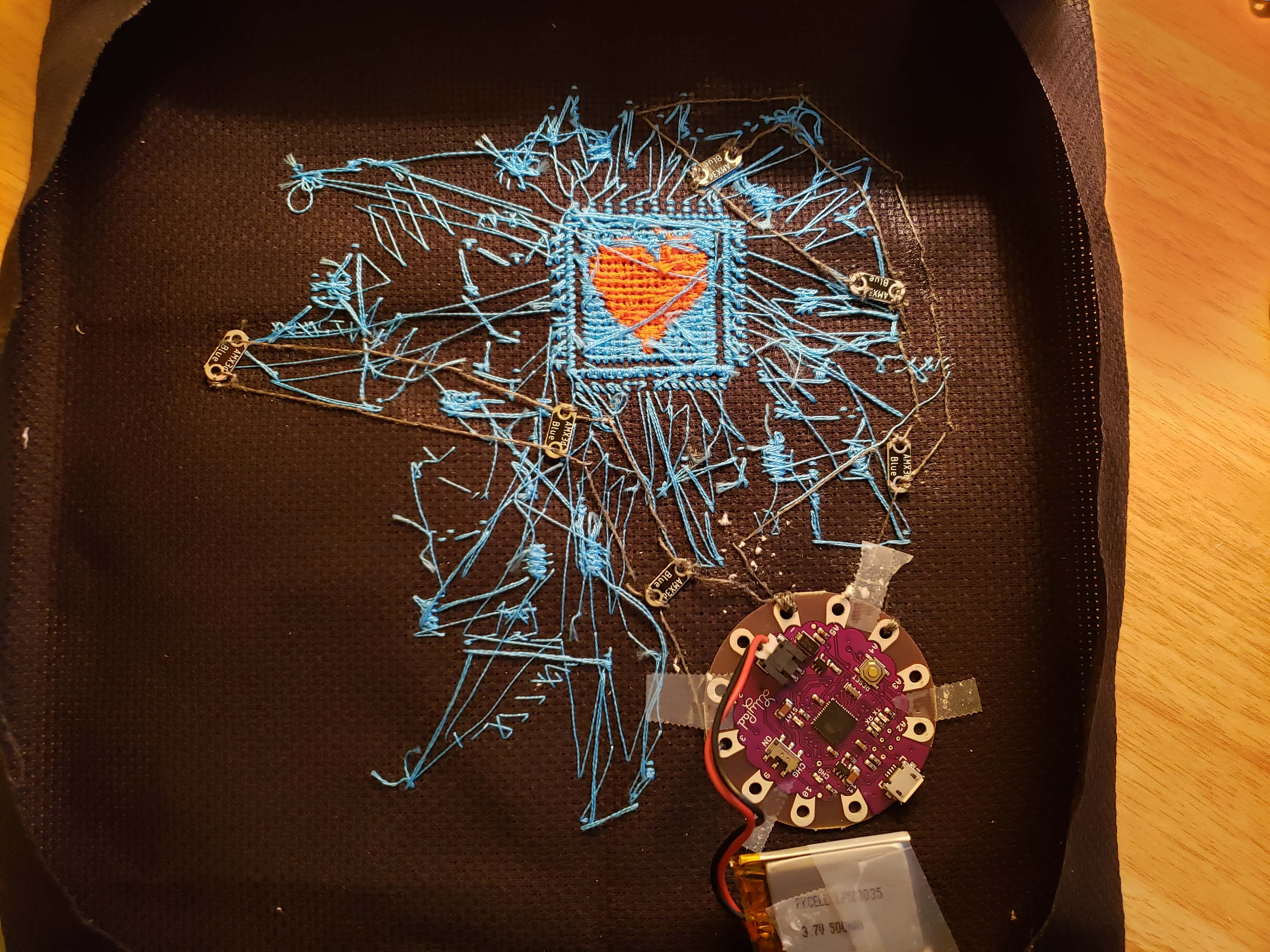
I wanted to connect multiple LEDs and program them to behave the same way for my project. The best approach for this is to daisy chain the LEDs and control them by the same GPIO pad on the LilyPad. In my project, I daisy-chained three LEDs connected to GPIO pad 3 (and ground), and another three LEDs are connected to the analog GPIO pad A4 (and ground).
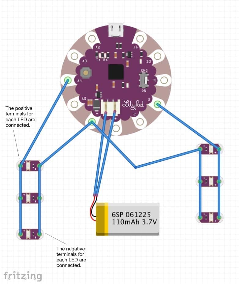
Based on the setup above, I programmed the LEDs to light up one strand and then the other in a loop. This is what the stitching looks like for the finished circuit.
Cross Stitch the Picture
During this step, cross stitch the picture just like you usually would, but honor any pattern changes you'd like to make to accommodate the LEDs added in a future step.
Programming the LilyPad
The program for turning the two strands of LEDs on and off is pretty straightforward. You can copy the sketch for the program from Github. Here's a breakdown of how it works.
The lines below are variables that set which pads the two LED strands will use.
1// Set which pad each strand of lights is connected to 2int lightStrand1 = A4; 3int lightStrand2 = 3;
The setup function is run once the LilyPad starts the program and sets the pin mode for the two LED strands as outputs. This means that pads A4 and 3 will behave as outputs (instead of inputs) so that we can update them in the loop function. (Note: For most microcontrollers, the pads are referred to as pins because they're actually pins connected to the board. The "pads" on the LilyPad are the same as "pins" on other microcontrollers hence the use of pin in the function name.)
The Serial.begin(9600) sets the rate at which serial data is transferred in bits per second (aka, baud). It helps keep the the flow of data in sync between two devices. The value generally used is 9600 as specified here.
1// Runs once
2void setup() {
3 // Set strands as outputs
4 pinMode(lightStrand1, OUTPUT);
5 pinMode(lightStrand2, OUTPUT);
6
7 // Initialize Serial, set the baud rate to 9600 bps
8 Serial.begin(9600);
9}
The loop function repeatedly runs after the setup function while the LilyPad has power. It pauses the loop for 1.5 seconds, turns on one LED strand while turning off the other, pauses for another 1.5 seconds, and reverses the LED strand that's turned on/off to give the alternating effect.
Setting the LED strand to HIGH turns on the LEDs, and setting it to LOW turns them off. Since we're using the pads as outputs, we can write the change to them using the digitalWrite function. Even though it's called digitalWrite, it will still work with the analog pads on the LilyPad, which is why we can use it with lightStrand1 on the A4 pad.
1void loop() {
2 // Pauses the loop for 1.5 seconds
3 delay(1500); // milliseconds
4
5 // Setting lightStrand1 to HIGH turns ON the LEDs connected to pin A4
6 // Setting lightStrand2 to LOW turns OFF the LEDs connected to pin 3
7 digitalWrite(lightStrand1, HIGH);
8 digitalWrite(lightStrand2, LOW);
9
10 // Pauses the loop for 1.5 seconds
11 delay(1500); // milliseconds
12
13 // Setting lightStrand1 to LOW turns OFF the LEDs connected to pin A4
14 // Setting lightStrand2 to HIGH turns ON the LEDs connected to pin 3
15 digitalWrite(lightStrand1, LOW);
16 digitalWrite(lightStrand2, HIGH);
17}
You can adjust the program to use more LED strands, use individual LEDs, alternate the light strands more or less quickly, etc. The basic program above is just a starting point based on my circuit design.
Getting the Program on Your LilyPad
You can use the Arduino IDE to put the program on your LilyPad following the steps below:
- Plug your LilyPad into the computer
- Open the
.inofile that you copied from Github in the Arduino IDE - Select the correct board from the Tools > Board menu. The Arduino LilyPad USB should be under Arduino AVR Boards > LilyPad Arduino USB. Choosing the right board is important; if you don't, you could mess up the bootloader.
- Select the correct port from the Tools > Port menu. It should look something like this on a Mac/Linux computer,
dev/cu.usbmodem####, or like this on a Windows computer,COM##. - Press the Publish button in the top left corner of the Arduino window (it looks like a right arrow). This will compile the program and publish it to your LilyPad.
Stitch the LEDs into the Cross-Stitch Picture and Connect Them to the LilyPad
Follow the guidance in the "Planning the Circuit" section above to stitch the LEDs into your picture in the desired configuration. It's helpful during this step to test the LEDs as you go so that you don't get to the end, find out that your circuit doesn't work, and have to redo it.
When testing your circuit, make sure that you don't connect the LilyPad to a power source until you've correctly connected the positive and negative threads from the LED(s) to the LilyPad. Otherwise, you could create a short circuit.
If you run into issues where your LEDs aren't lighting up as expected, make sure that:
- Positive and negative threads don't overlap
- Tail ends of tied off threads aren't brushing other threads
- The conductive thread is tightly wrapped around the terminals on the LEDs and the LilyPad pads multiple times to ensure a good connection
- The battery has sufficient charge (you can test it with a multimeter)
Lightly Brush the Fabric Glue Over the Conductive Thread
Once you're happy with the picture, lightly brush a thin layer of fabric glue over the conductive thread. This will help protect the thread and keep it in place.
That's it! At this point, you should have a cross-stitch picture that incorporates LEDs.